Describe network architectures for the data center
Requirements for Cloud Networks:
- Availability
- Scalability
- Virtualization
- Consolidation
Cisco Unified Fabric
Describe the Cisco Nexus product family
The Cisco Nexus family of switches is designed to meet the stringent requirements of the next-generation data center. Not simply bigger or faster, these switches offer the following characteristics:
- Infrastructure that can be scaled cost-effectively and that helps you increase energy, budget, and resource efficiency
- Transport that can navigate the transition to 10 Gigabit Ethernet and unified fabric and can also handle architectural changes such as virtualization, Web 2.0 applications, and cloud computing.
- Operational continuity to meet your need for an environment where system availability is assumed and maintenance windows are rare if not totally extinct.
Access Layer Design:
- Top of Rack (TOR)
- Middle of Row (MoR) or End of Row (EoR)
Fabric Extender (FEX) – ‘remote’ line cards
Describe device virtualization
By using network virtualization solutions, network resources can be deployed and managed as logical services, rather than physical resources. As a result, companies can:
- Enhance enterprise agility.
- Improve network efficiency.
- Reduce capital and operational costs.
- Maintain high standards of security, scalability, manageability, and availability throughout the campus design.
Network virtualization solutions can consolidate multiple physical networks into one virtual network. They can also logically segment a single physical network into multiple logical networks. Partitions can be added to rapidly scale the network for business needs.
Virtual PortChannel (vPC)
A virtualization technology that presents both Cisco Nexus switches paired devices as a unique Layer 2 logical node to access layer devices or endpoints.
A vPC allows links that are physically connected to two different Cisco Nexus devices to appear as a single port channel to a third device. The third device can be a switch, server, or any other networking device that supports link aggregation technology. vPC provides the following technical benefits:
- Eliminates Spanning Tree Protocol (STP) blocked ports
- Uses all available uplink bandwidth
- Allows dual-homed servers to operate in active-active mode
- Provides fast convergence upon link or device failure
- Offers dual active/active default gateways for servers
vPC also leverages native split horizon/loop management provided by port-channeling technology: a packet entering a port-channel cannot immediately exit that same port-channel. By using vPC, users get the immediate operational and architectural advantages:
- Simplifies network design
- Build highly resilient and robust Layer 2 network
- Enables seamless virtual machine mobility and server high-availability clusters
- Scales available Layer 2 bandwidth, increasing bisectional bandwith
- Grows the size of the Layer 2 network
FabricPath Based ‘Fabric’ Design
Fabric – network that ‘behaves’ like a single device often deployed in a Spine-Leaf topology.
Spine – scales to provide fabric bandwidth
Leaf – scales to provide access port density
With FabricPath, you can create a flexible Ethernet fabric that eliminates many of the constraints of STP. At the control plane, FabricPath uses a Shortest-Path First (SPF) routing protocol to determine reachability and select the best path or paths to any given destination in the FabricPath domain. In addition, the FabricPath data-plane introduces capabilities that ensure the network remains stable, and provides scalable, hardware-based learning and forwarding capabilities not bound by software or CPU capacity.
Benefits of deploying a FabricPath-based Ethernet fabric include:
- Simplify and cost-reduce deployment and operation – FabricPath provides plug-and-play simplicity with minimal configuration. Application deployment becomes simpler while troubleshooting remains straightforward and transparent.
- Maximize flexibility – FabricPath removes many of the design constraints associated with STP, enabling simplified workload mobility, network clustering applications, and VLAN extension
- Increase available bandwidth – With capabilities such as equal-cost multipathing (ECMP) and multitopology forwarding, FabricPath enables you to leverage all available bandwidth in the network.
- Increase availability – FabricPath provides fast reconvergence and fault-domain isolation, insulating end users and applications from changes in the network.
In other words, while FabricPath benefits the server and application teams by providing a transparent network fabric that breaks down application silos, permits workload mobility, and provides maximum deployment flexibility, it also benefits the network operations team by reducing inter-team dependencies, streamlining deployment and configuration, and simplifying network maintenance and troubleshooting
Virtual Device Context (VDC)
The Cisco NX-OS software supports VDCs, which partition a single physical device into multiple logical devices that provide fault isolation, management isolation, address allocation isolation, service differentiation domains, and adaptive resource management. You can manage a VDC instance within a physical device independently. Each VDC appears as a unique device to the connected users. A VDC runs as a separate logical entity within the physical device, maintains its own unique set of running software processes, has its own configuration, and can be managed by a separate administrator.
VDCs also virtualize the control plane, which includes all those software functions that are processed by the CPU on the active supervisor module. The control plane supports the software processes for the services on the physical device, such as the routing information base (RIB) and the routing protocols.
SDN
Separation of control and data
Control Plane – makes the decisions for the network device that will decide what the device will do and how it does it (Operating System + CPU)
- Makes decisions about where traffic is sent
- Control plane packets are destined to or locally originated by the router itself
- The control plane functions include the system configuration, management, and exchange of routing table information
- The route controller exchanges the topology information with other routers and constructs a routing table based on a routing protocol, for example, RIP, OSPF or BGP
- Control plane packets are processed by the router to update the routing table information.
- It is the Signalling of the network
- Since the control functions are not performed on each arriving individual packet, they do not have a strict speed constraint and are less time-critical
Data Plane – actually forwards packets (ASIC)
- Also known as Forwarding Plane
- Forwards traffic to the next hop along the path to the selected destination network according to control plane logic
- Data plane packets go through the router
- The routers/switches use what the control plane built to dispose of incoming and outgoing frames and packets
In SDN, there is a device known as a SDN controller which acts as the control plane and then connects to the various physical devices which represent the data plane. The SDN Controller also connects to various applications, such as an orchestrator, who will then work with the SDN Controller to make various changes to the network devices.
Programmability
There are three use cases to defining what SDN automation and programmability:
- Adjusting the Flows – This use case focuses on protocols — such as OpenFlow — that enable SDN Controllers to interact with routers and switches in the forwarding plane so adjustments can be made as to how the traffic flows through SDN networks. This helps networks respond to changing demands.
- Supporting the Applications – This use case is interested in concerned with the coordination, automation, and exception handling of a network to, better align with the needs of the applications running on it. Typically for this use case, network operators are looking to extend network capabilities to automate the configuration of the routers and switches in a scalable manner to support rapid deployment of a large number of new applications, services, and infrastructure to quickly meet an organization’s requirements as it changes. Nick Lippis, co-founder of the Open Networking Users Group (ONUG) points out “Since we are moving into a model of automated workload creation, enterprises want to do what you can do in Amazon [Web Services] – put up a workload and configure storage and network [and] the whole cloud infrastructure. But they can’t because…they need a way in which a dependency map gets created automatically.” There needs to be a language, such as Javascript Object Notation (JSON) or Extensible Messaging and Presence Protocol (XMPP) that can be shared to generate a ‘cross-domain’ response to these needs.
- Automating SDN Networks – This use case focuses on SDN networks doing what they are supposed to do without interference from a network administrator. When something changes, the network should figure out how to address the change automatically.
Much of the programmability of the network relies on the northbound and southbound open application programmable interfaces (APIs) communications between the SDN Controller and the applications and switches/routers, respectively. Regardless of which camp an organization fits into, additional programmability of the network can enable better bandwidth utilization, improved application performance, and maximum operational efficiency.
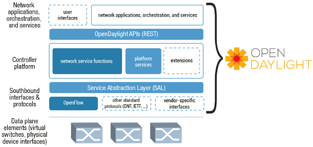
Basic understanding Open Daylight
Open Daylight is an open source project formed under the Linux Foundation with the mutual goal of furthering the adoption and innovation of Software Defined Networking (SDN) through the creation of a common industry-supported framework–essentially we are building a open source SDN stack.
OpenDaylight has created an industry-supported framework that should help the SDN market accelerate. The Project mitigates much of the risk for customers around SDN adoption; meanwhile, for developers, there is a common industry-backed framework which can simplify their lives. The hope is for things to progress well beyond this with the emergence of an a rich ecosystem that delivers commercial offerings, tools, services and support.

ACI
Overview of Cisco Application Centric Infrastructure
Cisco ACI is a new data center architecture designed to address the requirements of today’s traditional networks, as well as to meet emerging demands that new computing trends and business factors are placing on the network.
A high-level summary of its main building blocks is presented here.
Describe how ACI solves the problem not addressed by SDN
Application-Centric Policy Model Using Group-Based Policy
To provide agility and simplicity in data center infrastructure, a new language describing the abstracted intent of connectivity is required so that the end user doesn’t need significant networking knowledge to describe the requirements for connectivity. Additionally, this intent should be decoupled from network forwarding semantics so that the end user can describe the policy in such a way that a change in policy need not affect forwarding behavior, and the converse.
Because this abstracted, decoupled policy model did not exist prior to Cisco ACI, Cisco created such a model. It is called group-based policy (GBP) and is a working project in OpenStack and OpenDaylight.
OpenDaylight describes group-based policy as “an application-centric policy model… that separates information about application connectivity requirements from information about the underlying details of the network infrastructure.”
This approach offers a number of advantages, including:
- Easier, application-focused way of expressing policy: By creating policies that mirror application semantics, this framework provides a simpler, self-documenting mechanism for capturing policy requirements without requiring detailed knowledge of networking.
- Improved automation: Grouping constructs allow higher-level automation tools to easily manipulate groups of network endpoints simultaneously.
- Consistency: By grouping endpoints and applying policy to groups, the framework offers a consistent and concise way to handle policy changes.
- Extensible policy model: Because the policy model is abstract and not tied to specific network implementations, it can easily capture connectivity, security, Layer 4 through 7, QoS, etc.
Cisco ACI makes extensive use of group-based policy in its application-centric policy model, in which connectivity is defined by consolidating endpoints (physical or virtual) into endpoint groups (EPGs). Connectivity is defined when the end user specifies a contractual relationship between one EPG and another. The end user does not need to understand the protocols or features that are employed to create this connectivity.
ACI Open Framework
Cisco ACI supports an extensible partner ecosystem that includes Layer 4 through 7 services; hypervisors; and management, monitoring, and cloud orchestration platforms. All use Cisco ACI’s open APIs and development kits, device packages, and plug-ins, as well as a new policy protocol, OpFlex, which is used to exchange group-based policy information.
- Open APIs: Cisco ACI supports API access through REST interfaces, GUIs, and the CLI as well as a number of software development kits (kits for Python and Ruby are available today). Cisco APIC supports a comprehensive suite of REST APIs over HTTP/HTTPS with XML and JSON encoding bindings. The API provides both class-level and tree-oriented data access. REST is a software architecture for distributed systems. It has emerged over the past few years as a leading web services design model and has increasingly displaced other design models such as Simple Object Access Protocol (SOAP) and Web Services Description Language (WSDL) because of its simpler approach.
- Partner ecosystem and OpFlex: OpFlex, the southbound API, is an open and extensible policy protocol used to transfer abstract policy in XML or JSON between a policy controller, such as Cisco APIC, and any device, including hypervisor switches, physical switches, and Layer 4 through 7 network services. Cisco and its partners, including Intel, Microsoft, Red Hat, Citrix, F5, Embrane, and Canonical, are working through the IETF and open source community to standardize OpFlex and provide a reference implementation.
OpFlex is a new mechanism for transferring abstract policy from a modern network controller to a set of smart devices capable of rendering policy. Whereas many existing protocols such as the Open vSwitch Database (OVSDB) management protocol focus on imperative control with fixed schemas, OpFlex is designed to work as part of a declarative control system, such as Cisco ACI, in which abstract policy can be shared on demand. One major benefit of this model is the capability to expose the complete feature set of an underlying device, allowing differentiation of hardware and software objects such as Layer 4 through 7 devices.
In addition to its implementations in the open source community, OpFlex is one of the primary mechanisms through which other devices can exchange and enforce policy with Cisco APIC. OpFlex defines that interaction. As a result, by integrating a number of devices from both Cisco and ecosystem partners using Cisco ACI, organizations can use it to gain investment protection
How Cisco ACI Addresses the New SDN Challenges
Although SDN, software-based virtual overlays, and OpenFlow present some interesting solutions for both traditional and emerging computing workloads, except in academic and research institutions, few data centers have adopted software overlays and OpenFlow.
A next-generation SDN-based architecture must address all these challenges. Cisco ACI accomplishes this in context of the modern data center.
- Software-based virtual overlays are difficult to manage and troubleshoot: Cisco ACI does not rely solely on software-based virtual overlays for fabricwide connectivity. Although Cisco ACI does deploy an overlay, it is instantiated in hardware, and the management features of Cisco ACI have enough intelligence to provide full coordination and contextualization to show what services are affected by failures in the underlay or overlay network.Note that Cisco ACI supports software-based overlays that either terminate on the Cisco ACI fabric or run over the top. These are completely optional modes of deployment, and the end user can decide how to deploy workloads. The point is that Cisco ACI does not rely on software-based overlays to achieve the flexibility and agility sought in SDN.
- OpenFlow protocols are too primitive and concrete for the data center: In addition to providing automation and flexibility, Cisco ACI introduces a new model to describe connectivity in the data center through group-based policy. Because the policy intent is abstracted, the end user can define how certain “things” connect to other “things” in the data center. This abstracted view of policies is a lot easier for cloud orchestration tools, applications, and security administrators to consume than is the case with OpenFlow protocols.
- Merchant silicon is not optimized for OpenFlow today: Cisco ACI uses a combination of merchant silicon and custom silicon developed by Cisco to provide the right level of capabilities at scale, while still delivering the solution at an attractive price. The custom silicon embedded in the Cisco Nexus® 9000 Series Switches includes memory table structures optimized so that certain functions can be offloaded to the on-board merchant silicon, with the custom silicon dedicated to functions such as policy enforcement, encapsulation normalization, and VXLAN routing.
Describe benefits of leaf/spine architecture
A leaf/spine architecture has several desirable characteristics that play into the hands of network designers who need to optimize east-west traffic:
All east-west hosts are equidistant. Leaf-spine widens the access and aggregation layers. A host can talk to another host on any other leaf switch and know that the traffic will only traverse the ingress leaf switch, spine switch and egress leaf switch. As a result, applications running over this network infrastructure will behave predictably, which is a key feature for organizations running multi-tiered Web applications, high-performance computing clusters or high-frequency trading.
Leaf-spine uses all interconnection links. The traditional three-layer design uses spanning-tree, a loop prevention protocol. As mentioned earlier, spanning-tree detects loops, and then block links forming the loop. This means that dual-homed access switches only use one of their two uplinks. Modern alternatives such as SPB and TRILL allow all links between leaf and spine to forward traffic, allowing the network to scale as traffic grows.
It supports fixed configuration switches. Fixed configuration switches ship with a specific number of ports, compared with chassis switches, which feature modular slots that can be filled with line cards to meet port density requirements. Chassis switches tend to be costlycompared to fixed configuration switches. But chassis switches are necessary in traditional three-layer topologies where large numbers of switches from one layer connect to two switches at the next layer. Leaf-spine allows for interconnections to be spread across a large number of spine switches, obviating the need for massive chassis switches in some leaf-spine designs. While chassis switches can be used in the spine layer, many organizations are finding a cost savings in deploying fixed-switch spines.
Leaf-spine is currently the favored design for data center topologies of almost any size. It is predictable, scalable and solves the east-west traffic problem. Any organization whose IT infrastructure is moving towards convergence and high levels of virtualization should evaluate a leaf-spine network topology in their data center.
Describe the role of APIC Controller
Cisco APIC serves as the single point of automation and fabric element management in both physical and virtual environments. As a result, operators can build fully automated and scalable multitenant networks.
Cisco APIC attributes and features include the following:
- The ability to build and enforce application centric network policies
- An open framework through northbound and southbound APIs
- Integration of third-party Layer 4 through 7 services, virtualization, and management
- Intelligent telemetry and visibility for applications and tenants
- The ability to provide security for multitenant environments at scale
- A common policy platform for physical, virtual, and cloud networking
The Cisco APIC framework enables broad ecosystem and industry interoperability with Cisco ACI. It enables interoperability between a Cisco ACI environment and management, orchestration, virtualization, and Layer 4 through 7 services from a broad range of vendors.
Cisco APIC provides centralized access to your Cisco ACI through an object-oriented RESTful API framework with XML and JSON binding. It also supports a modernized, user-extensible command-line interface (CLI) and GUI. APIs have full read and write access to the Cisco ACI, providing tenant- and application-aware programmability, automation, and system access.
Northbound APIs allow rapid integration with existing management and orchestration frameworks. They also allow integration with OpenStack interfaces to provide Cisco ACI policy consistency across physical, virtual, and cloud environments.
Southbound APIs let you extend Cisco ACI policies to existing virtualization and Layer 4 through 7 service and networking components. They will support computing and storage environments in the future. Cisco has submitted to the IETF the OpFlex protocol, which is intended to maintain control intelligence in the network infrastructure instead of centralizing it in a separate controller. The goal is to make the OpFlex draft, supported with partners IBM, Plexxi and Midokura, an open source version of the Cisco API data model to foster a broader ecosystem.
In general, people want policies that are consistent across the entire network. However, one of the main challenges in managing policies in existing networks is the number of devices to which policies need to be applied coupled with the need to ensure consistency. The Cisco Application Policy Infrastructure Controller (APIC) addresses this issue.
Cisco APIC is a distributed system implemented as a cluster of controllers. It provides a single point of control, a central API, a central repository for global data, and a repository for group-based policy data for Cisco ACI.
Cisco APIC is a unified point for policy-based configuration expressed through group-based policy (Figure 3). The primary function of Cisco APIC is to provide policy authority and policy resolution mechanisms for the Cisco ACI fabric and devices attached to the fabric. Automation is provided as a direct result of policy resolution and renders its effects on the Cisco ACI fabric, so that end users no longer have to touch each network element and manually make sure that all policies are configured appropriately. Note that Cisco APIC is not involved in forwarding calculations or route provisioning, which provides additional scalability, stability, and performance.

Cisco APIC communicates with the Cisco ACI fabric to distribute policies to the points of attachment and provide several critical administrative functions to the fabric. Cisco APIC is not directly involved in data-plane forwarding, so a complete failure or disconnection of all Cisco APIC elements in a cluster will not result in any loss of forwarding capabilities, increasing overall system reliability.
In general, policies are distributed to nodes as needed upon endpoint attachment or by an administrative static binding, allowing greater scalability across the entire fabric.
Cisco APIC also provides full native support for multitenancy so that multiple interested groups (internal or external to the organization) can share the Cisco ACI fabric securely, yet still be allowed access to shared resources if required. Cisco APIC also has full, detailed support for role-based access control (RBAC) down to each managed object in the system, so that privileges (read, write, or both) can be granted per role across the entire fabric.
Cisco APIC also has completely open APIs so that users can use Representational State Transfer (REST)-based calls (through XML or JavaScript Object Notation [JSON]) to provision, manage, monitor, or troubleshoot the system. Additionally, Cisco APIC includes a CLI and a GUI as central points of management for the entire Cisco ACI fabric.
Conclusion
The IT industry is going through a significant transformation, with BYOD, big data, cloud computing, IT as a service, and security now prominent concerns. At the same time, companies increasingly want to reduce overall IT spending (through reduction in both capital expenditures and operating expenses) and to provide much-improved levels of service to business units and functions by increasing overall IT agility. Many in the networking industry have cited SDN as the model to move the industry forward, but adoption of the prescribed technologies presents challenges.
Cisco ACI was developed not as a competitor to SDN, but as a catalyst to help promote the adoption of SDN throughout the IT industry: in essence, as an enabler of the SDN vision. Although some in the industry claim that Cisco ACI is not SDN, assessing Cisco ACI in the context of the definitions presented in the ONF SDN white paper shows that it does indeed meet the requirements of SDN. Cisco ACI also goes a step further, addressing areas that OpenFlow has not yet addressed.
Ultimately, the industry will be the final judge of whether Cisco ACI (and SDN) succeeds, but based on the current interest and adoption momentum, Cisco ACI is well positioned to become the new norm for data center networks.


